A study of the constitution and structure of all steels and irons must first start
with the iron-carbon equilibrium diagram. Many of the basic features of this system
(Fig. 1) influence the behavior of even the most complex alloy steels. For example,
the phases found in the simple binary Fe-C system persist in complex steels, but it
is necessary to examine the effects alloying elements have on the formation and
properties of these phases. The iron-carbon diagram provides a valuable foundation
on which to build knowledge of both plain carbon and alloy steels in their immense
variety.
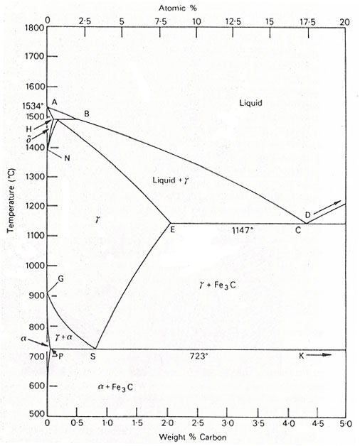
Fig. 1. The iron-carbon diagram.
It should first be pointed out that the normal equilibrium diagram really represents
the metastable equilibrium between iron and iron carbide (cementite). Cementite is
metastable, and the true equilibrium should be between iron and graphite. Although
graphite occurs extensively in cast irons (2-4 wt % C), it is usually difficult to
obtain this equilibrium phase in steels (0.03-1.5 wt %C). Therefore, the metastable
equilibrium between iron and iron carbide should be considered, because it is relevant
to the behavior of most steels in practice.
The much larger phase field of γ-iron (austenite) compared with that of
α-iron (ferrite) reflects the much greater solubility of carbon in γ-iron,
with a maximum value of just over 2 wt % at 1147°C (E, Fig.1). This high solubility
of carbon in γ-iron is of extreme importance in heat treatment, when solution
treatment in the γ-region followed by rapid quenching to room temperature allows
a supersaturated solid solution of carbon in iron to be formed.
The α-iron phase field is severely restricted, with a maximum carbon solubility
of 0.02 wt% at 723°C (P), so over the carbon range encountered in steels from
0.05 to 1.5 wt%, α-iron is normally associated with iron carbide in one form
or another. Similarly, the δ-phase field is very restricted between 1390 and
1534°C and disappears completely when the carbon content reaches 0.5 wt% (B).
There are several temperatures or critical points in the diagram, which are important,
both from the basic and from the practical point of view.
- Firstly, there is the A1, temperature at which the eutectoid reaction
occurs (P-S-K), which is 723°C in the binary diagram.
- Secondly, there is the A3, temperature when α-iron transforms to
γ-iron. For pure iron this occurs at 910°C, but the transformation
temperature is progressively lowered along the line GS by the addition of carbon.
- The third point is A4 at which γ-iron transforms to δ-iron,
1390°C in pure iron, hut this is raised as carbon is added. The A2,
point is the Curie point when iron changes from the ferro- to the paramagnetic
condition. This temperature is 769°C for pure iron, but no change in crystal
structure is involved. The A1, A3 and A4 points are
easily detected by thermal analysis or dilatometry during cooling or heating cycles,
and some hysteresis is observed. Consequently, three values for each point can be
obtained. Ac for heating, Ar for cooling and Ae (equilibrium}, but it should be
emphasized that the Ac and Ar values will be sensitive to the rates of heating and
cooling, as well as to the presence of alloying elements.
The eutectoid temperature is 723°C while the eutectoid composition is 0.80% C(s).
On cooling alloys containing less than 0,80% C slowly, hypo-eutectoid ferrite is
formed from austenite in the range 910-723°C with enrichment of the residual
austenite in carbon, until at 723°C the remaining austenite, now containing 0.8%
carbon transforms to pearlite, a lamellar mixture of ferrite and iron carbide
(cementite). In austenite with 0,80 to 2,06% carbon, on cooling slowly in the
temperature interval 1147°C to 723°C, cementite first forms progressively
depleting the austenite in carbon, until at 723°C, the austenite contains 0.8%
carbon and transforms to pearlite.
Steels with less than about 0.8% carbon are thus hypo-eutectoid alloys with ferrite
and pearlite as the prime constituents, the relative volume fractions being determined
by the lever rule which states that as the carbon content is increased, the volume
percentage of pearlite increases, until it is 100% at the eutectoid composition.
Above 0.8% C, cementite becomes the hyper-eutectoid phase, and a similar variation in
volume fraction of cementite and pearlite occurs on this side of the eutectoid
composition.
The three phases, ferrite, cementite and pearlite are thus the principle constituents
of the infrastructure of plain carbon steels, provided they have been subjected to
relatively slow cooling rates to avoid the formation of metastable phases.
The austenite- ferrite transformation
Under equilibrium conditions, pro-eutectoid ferrite will form in iron-carbon alloys
containing up to 0.8 % carbon. The reaction occurs at 910°C in pure iron, but
takes place between 910°C and 723°C in iron-carbon alloys.
However, by quenching from the austenitic state to temperatures below the eutectoid
temperature Ae1, ferrite can be formed down to temperatures as low as
600°C. There are pronounced morphological changes as the transformation
temperature is lowered, which it should be emphasized apply in general to hypo-and
hyper-eutectoid phases, although in each case there will be variations due to the
precise crystallography of the phases involved. For example, the same principles
apply to the formation of cementite from austenite, but it is not difficult to
distinguish ferrite from cementite morphologically.
The austenite-cementite transformation
The Dube classification applies equally well to the various morphologies of cementite
formed at progressively lower transformation temperatures. The initial development of
grain boundary allotriomorphs is very similar to that of ferrite, and the growth of
side plates or Widmanstaten cementite follows the same pattern. The cementite plates
are more rigorously crystallographic in form, despite the fact that the orientation
relationship with austenite is a more complex one.
As in the case of ferrite, most of the side plates originate from grain boundary
allotriomorphs, but in the cementite reaction more side plates nucleate at twin
boundaries in austenite.
The austenite-pearlite reaction
Pearlite is probably the most familiar micro structural feature in the whole science
of metallography. It was discovered by Sorby over 100 years ago, who correctly assumed
it to be a lamellar mixture of iron and iron carbide.
Pearlite is a very common constituent of a wide variety of steels, where it provides a
substantial contribution to strength. Lamellar eutectoid structures of this type are
widespread in metallurgy, and frequently pearlite is used as a generic term to describe
them.
These structures have much in common with the cellular precipitation reactions. Both
types of reaction occur by nucleation and growth, and are, therefore, diffusion
controlled. Pearlite nuclei occur on austenite grain boundaries, but it is clear that
they can also be associated with both pro-eutectoid ferrite and cementite. In
commercial steels, pearlite nodules can nucleate on inclusions.
List of Articles - Knowledge Base