The structures formed during the continuous
cooling of steel from above Ac3 can be understood best by studying the
constant-temperature (isothermal) transformation of austenite, thus separating the two variables:
time and temperature.
One method consists of heating small specimens
above Ac3 to form
austenite, then quenching into a suitable bath (e.g. liquid tin) at some
constant sub-critical temperature. After holding for selected periods of
time, the specimens are withdrawn from the bath and rapidly quenched in
cold water. This converts any untransformed austenite into martensite the
volume of which can be estimated microscopically. Another method consists
in measuring length changes caused by the decomposition of austenite at
the constant temperature by means of a dilatometer.
When carbon steel is quenched in the baths at constant temperatures,
the velocity of austenite transformation is found to depend on
temperature. The time for the beginning and completion of the
transformation of the austenite is plotted against the temperature to give
the Bain "S-curve", shown in Fig. 1, now called TTT-curve
(time-temperature-transformation).
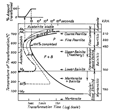
Figure 1. Ideal TTT-curve for 0,65%
carbon steel depicting time interval required for beginning, 50% and 100%
transformation of austenite at a constant temperature A=
Austenite F= Ferrite P = Pearlite
B = Bainite
The logarithmic scale of time is used to condense results
into a small space. Ae1 and Ae3 lines represent the equilibrium
transformation temperatures. Austenite is completely stable above Ae3 and
partially unstable between Ae3 and Ae1. Below Ae1 austenite is completely
unstable and transforms in time. Two regions of rapid transformation occur
about 550° and 250°C. The form of each of the curves and their positions
with respect to the time axis depend on the composition and grain size of
the austenite which is transforming.
The TTT-curve is most useful in presenting an overall
picture of the transformation behaviour of austenite. This enables the
metallurgist to interpret the response of steel to any specified
heat-treatment, to plan practical heat-treatment operations and to control
limited hardening or softening and the time of soaking.
The decomposition of austenite occurs according to three
separate but sometimes overlapping mechanisms and results in three
different reaction products: pearlitic, bainitic, martensitic.
Pearlitic
The upper dotted curve in Fig. 1 represents the beginning of
the formation of ferrite. The curve just below it indicates the beginnings
of the breakdown of the austenite remnant into a ferrite-carbide
aggregate. In the high-temperature pearlitic range in Fig. 1 the process
resembles the solidification of crystals from a liquid by the formation
and growth of nuclei of carbide followed by ferrite by side nucleation
with side and edge growth, Fig. 2a and b.
At 700°C the formation of nuclei is slow (i.e. incubation
period), then growth proceeds rapidly to form large pearlite colonies
covering several austenite grains in some cases. As the transformation
temperature is lowered to 500°C the incubation period decreases and the
pearlite becomes increasingly fine.
Large numbers of nuclei form in the austenite boundaries,
but growth is slower and this produces nodular troostite, Fig. 2a. In the
case of medium carbon steels the excess ferrite decreases in volume and
begins to show an acicular or Widmanstätten type of distribution. The
relative amounts of free ferrite to be expected after a given
heat-treatment is indicated by the size of the "austenite and ferrite"
field and by the temperature interval between Ae1 and
Ae3.
Bainitic
Between about 500° and 350°C initial nuclei are ferrite
which is coherent with the austenite matrix. Cementite then precipitates
from the carbon-enriched layer of austenite, allowing further growth of
the ferrite as shown in Fig. 2c.
The carbides tend to lie parallel to the long axis of the
bainite needle to form the typical open feathery structure of upper
bainite. Below 350°C coherent ferrite, supersaturated with carbon, forms
first and is then followed by the precipitation of carbide within the
ferrite needle, transversely at an angle of 55°. A proportion of the
carbide is Fe2,4C and the ferrite contains a little dissolved carbon. This
lower bainite structure is somewhat similar to lightly tempered martensite
(Fig. 2d).
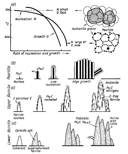
Figure 2. (a) Effect of different speeds of nucleation and
growth on formation of pearlite colonies; (b), (c), (d) diagrammatic
representation of formation of pearlite, upper bainite and lower bainite
Martensitic
In quenching down to about 250°C, the temperature drops
rapidly through the interval in which "nucleation" could take place, to a
temperature so low that the molecular mobility, i.e. diffusion, becomes
too small for the formation of nuclei.
In the third stage, therefore, the austenite changes
incompletely into a distorted body-centred structure, with little or no
diffusion of the carbon into particles of cementite, to form martensite
the plates of which are formed at a high speed (less than 0,002 sec). This
suggests that the mechanism of formation of this structure is not
nucleation and growth but a shearing process. This resembles the process
of mechanical twinning and involves very little atomic movement, but
considerable internal stress due to the shear and to the position of the
carbon atoms.
As the temperature decreases the elastic energy increases
and eventually causes a shear in a part of the matrix, which stabilises
the rest. Further shear can only occur when the temperature is lowered and
more energy gained. The amount of martensite formed, therefore, is
practically independent of time and depends principally on the
temperatures at which the steel is held. Hence a proportion of austenite
is usually retained in quenched steel which can be reduced in amount by a
decrease in temperature. This fact is used in sub-zero quenching.
The temperature at which martensite begins to form (Ms) is
progressively lowered as the carbon content of the steel increases,
e.g.
| C % |
0,02 |
0,2 |
0,4 |
0,8 |
1,2 |
| Ms °C |
520 |
490 |
420 |
250 |
150 |
The temperature is also affected by the alloy content, but
the following empirical formula (Steven and Haynes) can be used for
calculating Ms from the chemical analyses, provided all carbides have been
dissolved in the austenite:
Ms in °C = 561 - 474 (% C) - 33 (% Mn) - 17 (% Ni) - 17(%
Cr) - 21 (% Mo).
Mf is about 215°C below the Ms.
Plastic and elastic stresses promote the formation of
martensite, but it is retarded when cooling is interrupted. When cooling
is resumed after such a stabilisation arrest martensite only begins to
form again after cooling to a lower temperature.
The rate and extent of stabilisation (depression) depend on
the temperature and time of holding, amount of prior transformation and
alloy content.
Two forms of martensite have been identified depending on
carbon content. In low carbon steels laths containing many dislocations
are found, while in high carbon steels the plates are heavily twinned,
Fig. 3(a) and (b).
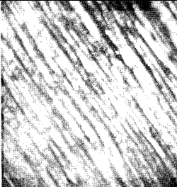
Figure 3. (a) Lathe martensite formed in 0,08°C steel quenched in brine from 100°C (x20000),
|
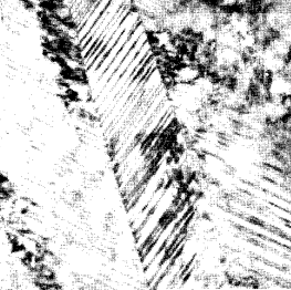
Figure 3. b) Twinned martensite in Fe30%Ni (x110000)
|
Two groups of phase transformation are now given the name
civilian, in which atoms move in a random manner (e.g. pearlite) and
military because of its orderly disciplined manner, e.g. martensite.
Martensite transformations also occur in non-ferrous alloys often
differing greatly from the rather special case in steel.
List of Articles - Knowledge Base